
Audionerdz / Vectra Documentation
VECTRA MAELSTROM | AEGIS DYNAMICS MODULE MANUAL
Public release edition 1.0 / May 2026 build behavior
A professional operating manual for Aegis Dynamics, the MAELSTROM dynamics module for leveling, punch, glue, linked multiband density shaping and sample-peak safety control inside VECTRA.
Aegis Dynamics at a glance
| Area | Summary |
|---|---|
| What Aegis Dynamics is | A dynamics and safety processor for leveling, punch, glue, linked multiband density shaping, and sample-peak output control. |
| Where it sits | Inside the MAELSTROM FX rack in VECTRA, alongside the other FX modules. |
| Core modes | Clean, Punch, Glue, Up/Dn MB, and Limit. |
| Band topology | Full, 2-Band, or 3-Band depending on the selected mode. Clean, Punch, and Glue can use any topology. Up/Dn MB requires multiband. Limit is Full-band only. |
| Multiband model | Linked multiband: global compression controls are shared, while crossovers and band trims are screen-local multiband controls. |
| Best uses | Transparent control, drum punch, bus glue, synth density, OTT-style multiband movement, taming harsh highs, controlling low-end weight, and final FX-chain safety. |
| Important safety fact | Limit is a sample-peak limiter. It is not a true-peak limiter and should not be described as one. |
A practical starting point is: choose the mode first, set Threshold / Amount / Mix until the gain movement feels right, then choose Full / 2-Band / 3-Band only when the source needs frequency-selective behavior.
Back to top1. Overview
Aegis Dynamics is the MAELSTROM dynamics module inside VECTRA. It can behave as a clean compressor, a punch shaper, a glue processor, a linked multiband upward/downward density tool, or a sample-peak safety limiter.
In a normal production workflow, Aegis sits inside the FX chain and performs one of four jobs:
- Control level without making the sound obviously processed.
- Shape impact so drums, plucks, and transients hit harder or sit more consistently.
- Glue material together with compression and a controlled saturation contribution.
- Protect the output with a final sample-peak ceiling.
The module is built around a central shield screen. In Full mode, the screen shows a transfer curve: input level on the horizontal axis and output level on the vertical axis. In 2-Band or 3-Band, the screen becomes a linked multiband editor with band regions, spectrum traces, crossover handles, trim handles, threshold position, and ceiling rail.
Aegis is designed to be fast. The lower rail contains the most important global controls, while multiband-specific edits happen directly on the screen through the multiband pills and handles.
Back to top2. Quick Start
2.1 Transparent full-band leveling
Use this when a source is uneven but you do not want an obvious compressor sound.
- Select Clean.
- Set Band Mode to Full.
- Leave Detector on Hybrid.
- Start around Ratio 2:1 to 4:1.
- Lower Threshold until the GR readout shows a few dB of movement.
- Keep Amount around 25-50% for gentle control.
- Use Mix at 100% for normal compression, or lower it for parallel control.
- Use Output or Makeup to match the bypassed level.
- Set Ceiling as a final safety limit, commonly around -1.0 dB.
2.2 Punch setup
Use this on drums, percussion, plucks, and short synth sounds that need more front-edge impact.
- Select Punch.
- Use Full for broadband punch or 2-Band / 3-Band when only part of the spectrum needs shaping.
- Start with Ratio 4:1.
- Set Attack slower than the fastest setting so the front of the transient can pass.
- Set Release so the gain reduction recovers before the next hit.
- Raise Amount until the hit becomes more defined.
- Use Mix to blend the punch layer back into the dry source.
2.3 Glue setup
Use this on layered synths, bass stacks, drum buses, and FX groups that should feel more connected.
- Select Glue.
- Start in Full.
- Use Ratio 2:1 to 4:1.
- Use moderate Attack and Release so movement follows the phrase rather than individual samples.
- Raise Amount until the layer starts to bind together.
- Use Soft Clip when you want a controlled rounded edge.
- Use Makeup or Auto Makeup to compensate level.
2.4 Up/Dn MB setup
Use this for OTT-style density, synth brightening, band-aware movement, and aggressive multiband shaping.
- Select Up/Dn MB.
- If Aegis was in Full mode, it will enter 3-Band automatically.
- Use 2-Band for simple low/high shaping, or 3-Band for low/mid/high control.
- Set Threshold where the band movement starts reacting.
- Set Ratio and Amount to decide the intensity.
- Use Up/Down Balance:
- -100% = downward compression only,
- 0% = downward and upward blended evenly,
- +100% = upward compression only.
- Use the screen-local crossovers to put the band splits around the material that matters.
- Use Low / Mid / High trim after the dynamics movement to rebalance tone.
- Keep Mix below 100% for parallel OTT-style results.
2.5 Limiter / safety setup
Use this as the final safety stage inside an FX chain.
- Select Limit.
- Aegis will use Full band mode; 2-Band and 3-Band are disabled.
- Set Ceiling to the desired sample-peak limit, for example -1.0 dB.
- Use Amount to push the signal toward the ceiling.
- Use Drive, Makeup, and Output carefully, because they can feed more level into the limiter.
- Watch OUT and the right-side output meter.
3. Interface Tour
Aegis has two working layouts: the compact card and the expanded panel.
3.1 Compact card
The compact card is the fast rack view. It shows the Aegis identity, mode selector, a small shield display, three header readouts, and three primary knobs.
The compact card is best for:
- choosing Clean / Punch / Glue / MB / Limit quickly,
- watching basic Threshold, GR, and OUT behavior,
- adjusting Threshold, Amount, and Mix while staying in the FX rack,
- confirming whether the module is working in Full, multiband, or Limit behavior.
In compact view, MB represents the Up/Dn MB mode on the small mode strip. The compact display condenses the visualizer and does not expose every lower-rail control.
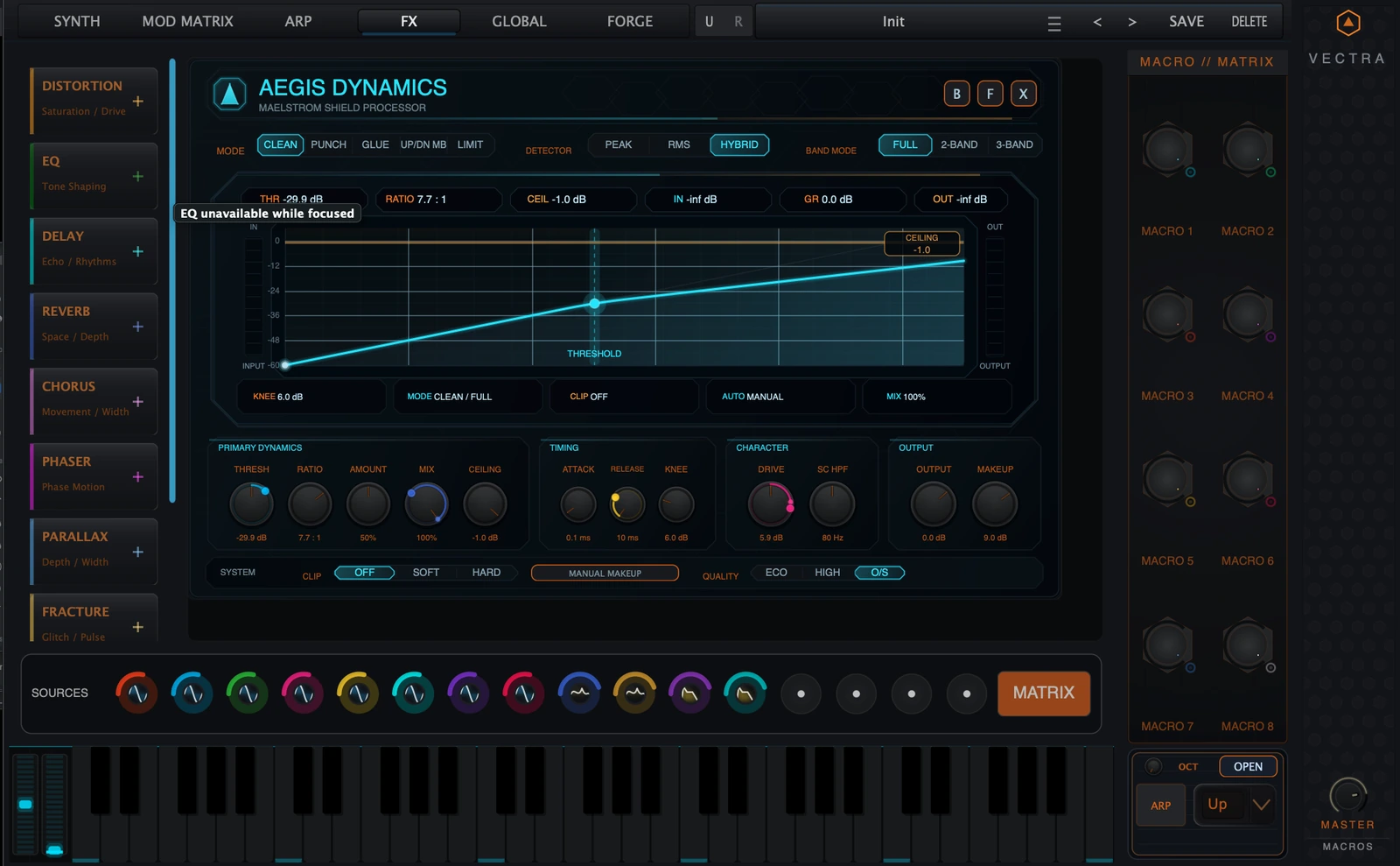
3.2 Expanded panel
The expanded panel is the full Aegis control surface. It contains:
- the identity header,
- B / F / X module-frame buttons,
- Mode strip,
- Detector strip,
- Band Mode strip,
- shield screen,
- live header chips,
- screen-local multiband pills,
- lower global control rail,
- system strip with Clip, Makeup state, and Quality.
Use expanded view whenever you need precise compression setup, multiband editing, or visual confirmation of gain movement.
3.3 Shield screen
The shield screen is the center of the module.
In Full mode, it shows:
- transfer curve,
- threshold handle,
- ceiling rail,
- compression pressure area,
- input and output meters,
- gain-reduction and output readouts.
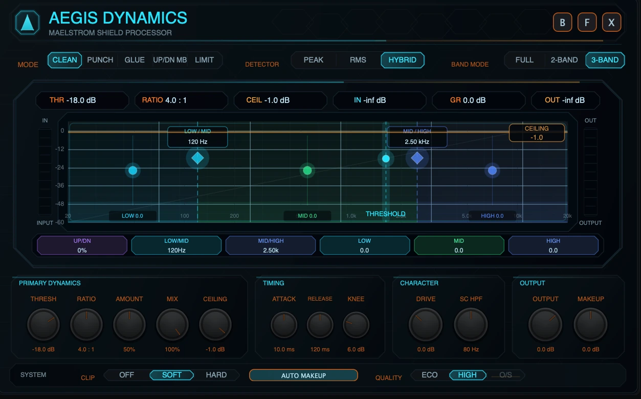
In 2-Band / 3-Band, it shows:
- band regions,
- live spectrum trace,
- low/high or low/mid/high band handles,
- crossover handles,
- per-band trim handles,
- per-band gain-reduction visualization,
- threshold marker,
- ceiling rail.
3.4 Header chips
In expanded view, the top of the screen shows six readouts:
| Chip | Meaning |
|---|---|
| THR | Current threshold. |
| RATIO | Current ratio. |
| CEIL | Current output ceiling. |
| IN | Current input peak readout. |
| GR | Current gain reduction readout. |
| OUT | Current output peak readout. |
In compact view, the readouts are condensed to THR, GR, and OUT.
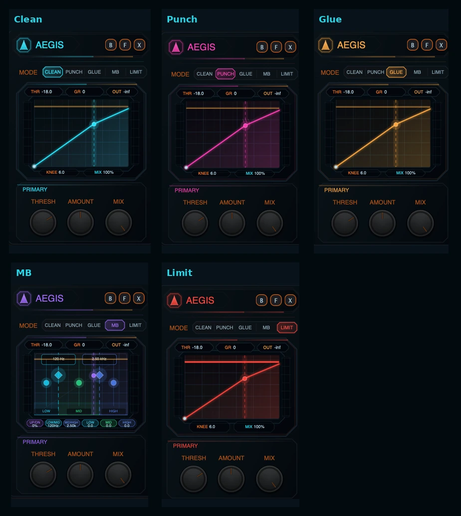
3.5 Mode strip
The Mode strip selects the main dynamics behavior:
- Clean
- Punch
- Glue
- Up/Dn MB
- Limit
Mode color changes across the panel. Clean is cyan, Punch is magenta, Glue is amber, Up/Dn MB is purple, and Limit is red.
3.6 Detector strip
The Detector strip selects how the compressor listens to the signal:
- Peak responds quickly to short peaks.
- RMS responds more to sustained energy.
- Hybrid blends peak and RMS behavior and is the default.
Detector choice affects both full-band compression and per-band detection in multiband modes.
3.7 Band Mode strip
The Band Mode strip selects topology:
- Full: one broadband dynamics path.
- 2-Band: linked low/high split.
- 3-Band: linked low/mid/high split.
Clean, Punch, and Glue can use Full, 2-Band, or 3-Band. Up/Dn MB requires 2-Band or 3-Band. Limit is Full-band only.
3.8 Screen-local multiband controls
When Band Mode is 2-Band or 3-Band, the screen shows multiband pills below the plot.
In 3-Band, the screen-local pills are:
| Pill | Meaning |
|---|---|
| Up/Dn | Up/Down Balance. |
| Low/Mid | Low/Mid crossover frequency. |
| Mid/High | Mid/High crossover frequency. |
| Low | Low-band trim. |
| Mid | Mid-band trim. |
| High | High-band trim. |
In 2-Band, the screen-local pills are:
| Pill | Meaning |
|---|---|
| Up/Dn | Up/Down Balance. |
| Split | The linked low/high split point. |
| Low | Low-band trim. |
| High | High-band trim. |
The lower hardware-style knob rail stays focused on global controls. Multiband edits live on the shield screen.
3.9 Lower control rail
The lower rail is organized into four groups.
| Group | Controls |
|---|---|
| Primary Dynamics | Threshold, Ratio, Amount, Mix, Ceiling. |
| Timing | Attack, Release, Knee. |
| Character | Drive, SC HPF. |
| Output | Output, Makeup. |
These controls remain global in every topology. In multiband modes, the same settings are applied to the linked band processors.
3.10 System strip
The bottom system strip contains:
| Control | Options | Function |
|---|---|---|
| Clip | Off / Soft / Hard | Clipping stage after dynamics and before final output limiting. |
| Makeup state | Auto Makeup / Manual Makeup | Toggles automatic makeup compensation. |
| Quality | Eco / High / O/S | Chooses analyzer/audio quality behavior. O/S is full-band clip-only. |
4. Modes
4.1 Clean
Clean is the general-purpose compression mode. Use it for leveling, controlling peaks, smoothing synth patches, and keeping an FX chain stable without adding a strong character.
What it does
Clean applies the main compression curve using the global Threshold, Ratio, Attack, Release, Knee, Amount, Makeup, Output, Mix, and Ceiling controls. Amount scales how strongly the gain reduction is applied. Clean also uses a slightly more forgiving soft-knee behavior as Amount increases, which helps it stay smooth at stronger settings.
When to use it
- Transparent leveling.
- Bass or synth control.
- Smoothing modulation-heavy patches.
- Light bus control before other MAELSTROM effects.
Recommended starting points
| Goal | Suggested start |
|---|---|
| Subtle leveling | Threshold just below peaks, Ratio 2:1, Amount 25-40%, Attack 10-30 ms, Release 80-200 ms. |
| Stronger control | Ratio 4:1, Amount 50-70%, Knee 6-12 dB, Mix 70-100%. |
| Parallel control | Mix 30-70%, more Threshold/Ratio/Amount than normal, match Output by ear. |
4.2 Punch
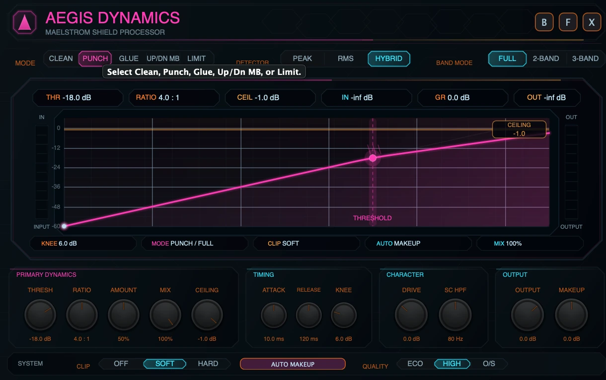
Punch is for shaping impact and definition. It is useful when a sound should feel more forward, snappier, or better separated from the rest of the mix.
What it does
Punch uses the same global dynamics control family, but it is presented and visualized as the transient-forward mode. In practice, the most important Punch moves are Attack, Release, Threshold, Amount, and Mix. Slower Attack lets more transient through before compression acts. Shorter Release can restore level before the next hit.
Punch does not add a separate transient synthesizer. The punch comes from compression timing, ratio, amount, and parallel blend.
When to use it
- Drums and percussion.
- Plucks and arps.
- Bass attacks.
- Short synth stabs.
- Material that should cut through without simply raising level.
Recommended starting points
| Goal | Suggested start |
|---|---|
| Drum snap | Ratio 4:1, Attack 10-30 ms, Release 50-150 ms, Amount 40-70%, Mix 50-100%. |
| Subtle transient support | Ratio 2:1 to 4:1, Amount 20-40%, Mix 30-60%. |
| Aggressive impact | Lower Threshold, Ratio 6:1 or higher, Amount 60-100%, then reduce Mix until the groove returns. |
4.3 Glue
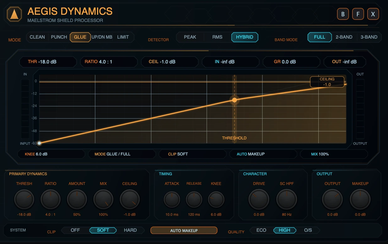
Glue is for making multiple layers feel more connected. It combines compression with a controlled saturation contribution.
What it does
Glue applies the main compression path and adds a gentle saturation component that increases with Amount. The saturation contribution is intentionally controlled and should be treated as density and edge, not as a separate distortion module.
When to use it
- Layered basses.
- Synth stacks.
- Drum buses.
- FX groups.
- Any source that needs more shared movement and density.
Recommended starting points
| Goal | Suggested start |
|---|---|
| Bus glue | Ratio 2:1 to 4:1, Attack 10-30 ms, Release 120-300 ms, Amount 25-50%. |
| Dense synth layer | Ratio 4:1, Amount 50-75%, Soft Clip on, Mix 60-100%. |
| Warm parallel glue | Stronger Threshold/Amount, Mix 30-60%, Output matched by ear. |
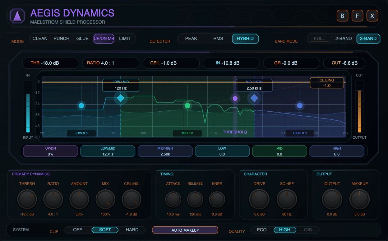
4.4 Up/Dn MB
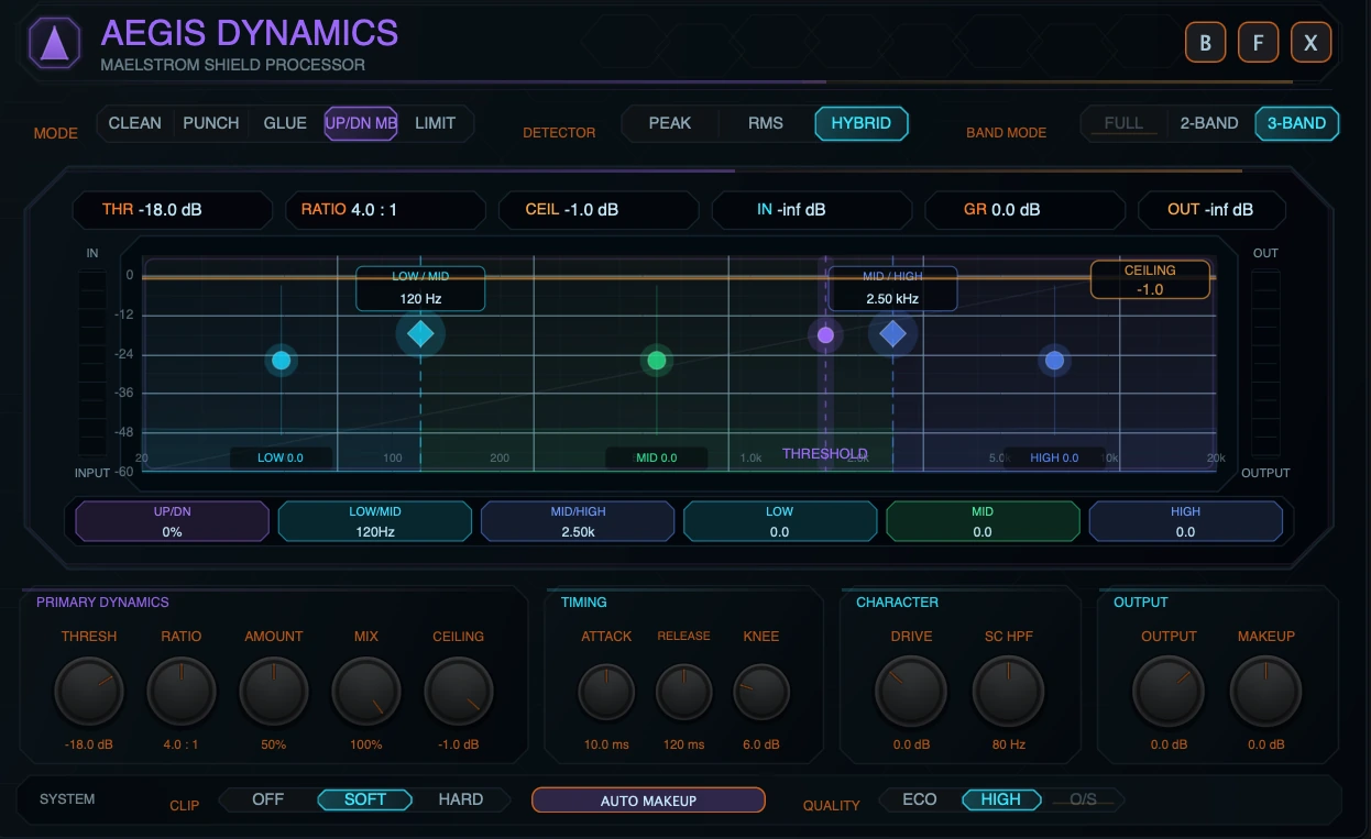
Up/Dn MB is the linked multiband upward/downward compression mode. It is the Aegis mode for OTT-style density, exaggerated detail, multiband movement, and frequency-aware shaping.
What it does
Up/Dn MB splits the signal into 2 or 3 linked bands. Each band reacts to its own energy, but the main compression settings remain global. Downward compression reduces material above the threshold. Upward compression raises material below the threshold, with protection against pulling up deep silence and noise-floor content too aggressively.
Topology rule
Up/Dn MB cannot run in Full mode. If it is selected while Aegis is in Full, the UI opens it as 3-Band by default. Users can then choose 2-Band or 3-Band.
Up/Down Balance
| Balance | Behavior |
|---|---|
| -100% | Downward compression only. Best for control and tightening. |
| 0% | Equal blend of downward and upward action. Best for classic density movement. |
| +100% | Upward compression only. Best for bringing out detail, tails, and low-level texture. |
When to use it
- OTT-style synth brightening.
- Band-aware density and movement.
- Controlling lows while lifting highs.
- Making quiet details more audible.
- Aggressive sound-design compression.
Recommended starting points
| Goal | Suggested start |
|---|---|
| Controlled multiband compression | 3-Band, Up/Down -100% to -40%, Ratio 4:1, Amount 40-70%. |
| OTT-ish density | 3-Band, Up/Down around 0%, Ratio 4:1 to 8:1, Amount 50-80%, Mix 30-70%. |
| Detail lift | Up/Down +30% to +100%, moderate Threshold, moderate Amount, avoid over-boosting noise/tails. |
| Low/high split shaping | 2-Band, place Split around the problem area, trim Low/High after dynamics. |
4.5 Limit
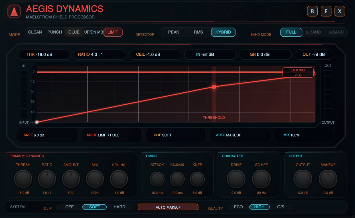
Limit is the sample-peak safety mode.
What it does
Limit uses a final sample-peak ceiling to keep the output samples from exceeding the Ceiling setting. The limiter is placed after dry/wet mix, so the final mixed output is still subject to the ceiling.
In Limit mode, the compressor gain-reduction stage is bypassed as the main behavior. The important limiting controls are Ceiling, Amount, Drive, Makeup, Output, Mix, and Clip. Amount can push the signal toward the ceiling before the final limiting stage.
Topology rule
Limit is Full-band only. Selecting Limit forces Full-band display and disables 2-Band and 3-Band.
When to use it
- Final safety at the end of a MAELSTROM FX chain.
- Catching peaks after drive, modulation, or other FX modules.
- Creative level push into a visible ceiling.
Recommended starting points
| Goal | Suggested start |
|---|---|
| Safety only | Ceiling -1.0 dB, Amount 0-25%, Drive 0 dB, Output 0 dB. |
| Controlled push | Ceiling -1.0 dB, Amount 25-60%, watch OUT and limiter reduction. |
| Aggressive ceiling effect | Higher Amount or Drive, Soft Clip optional, then reduce Output if the limiter works too hard. |
5. Band Mode
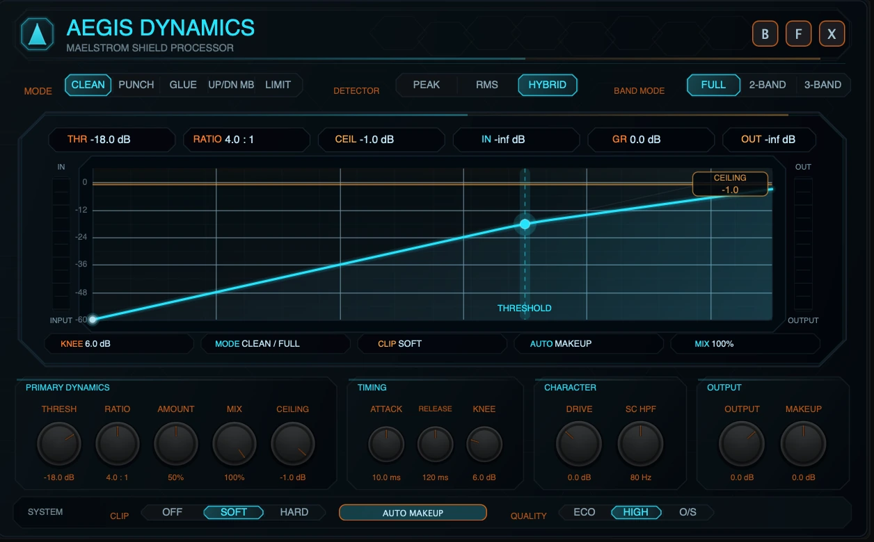
5.1 Full
Full processes the signal as one broadband path. Use it when the entire sound should react together.
Full is usually best for:
- transparent leveling,
- bus glue,
- broad punch shaping,
- final sample-peak limiting,
- simple setups where multiband movement would be unnecessary.
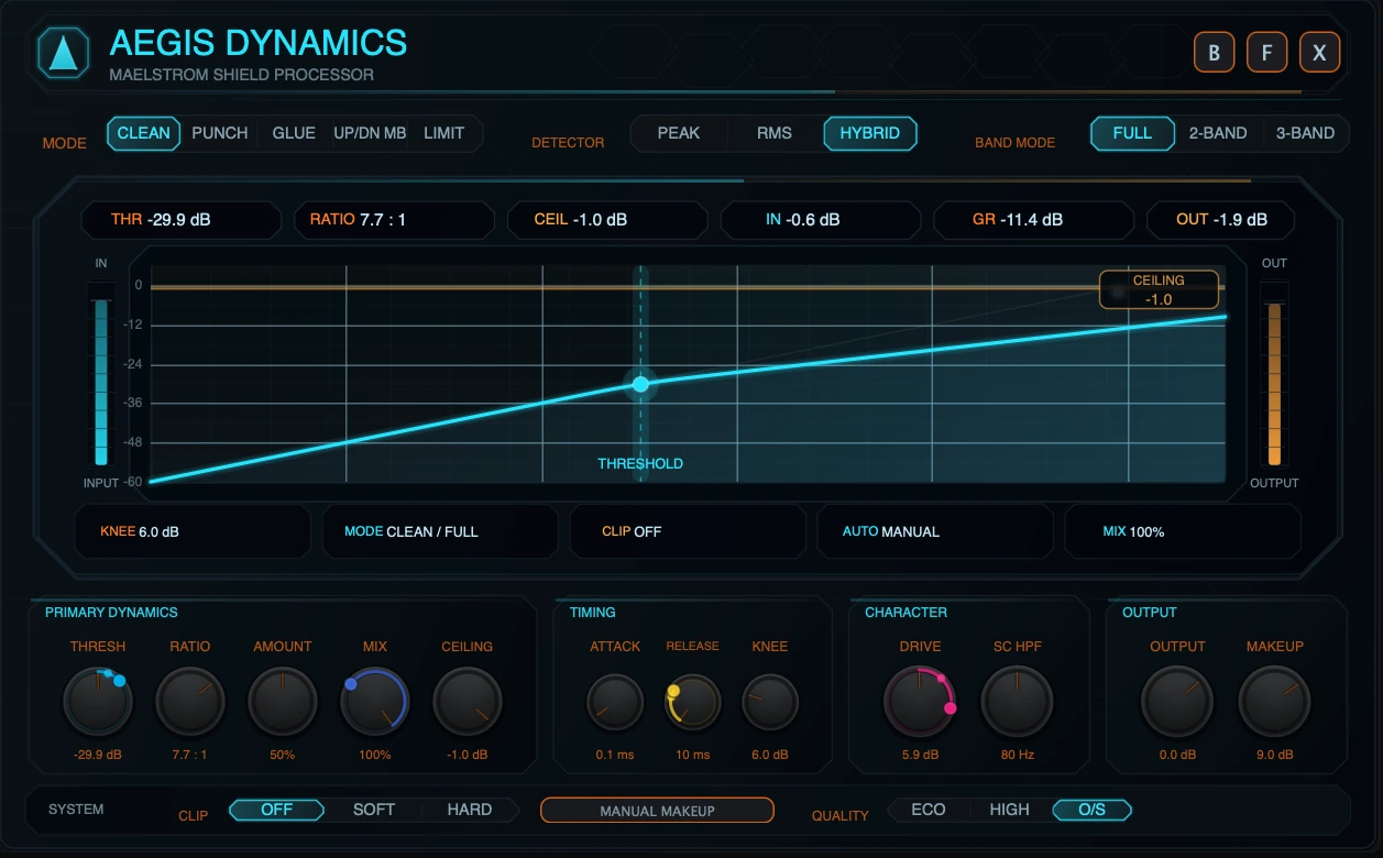
In Full mode, the screen shows the transfer curve, threshold handle, ceiling rail, input/output meters, and readout chips.
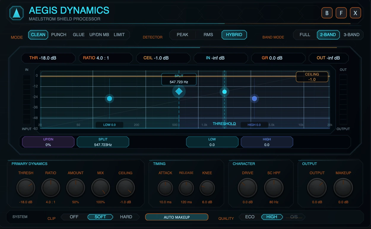
5.2 2-Band
2-Band splits the signal into linked low and high regions. The screen shows a single Split control plus Low and High trims.
Use 2-Band when:
- the low end needs different movement from the rest of the source,
- highs should be controlled or lifted without changing the low band too much,
- you want multiband behavior but do not need a separate mid band.
Aegis stores Low/Mid and Mid/High crossover parameters internally, but 2-Band presents them as one linked split. The split point is derived from the crossover pair and displayed as Split in the screen-local multiband controls.
5.3 3-Band
3-Band splits the signal into Low, Mid, and High regions.
Use 3-Band when:
- the low end, body, and air need separate tone balancing,
- you want OTT-style shaping,
- harshness lives in a different band from weight and brightness,
- the source benefits from visible low/mid/high energy feedback.
3-Band exposes:
- Low/Mid crossover,
- Mid/High crossover,
- Low trim,
- Mid trim,
- High trim.
5.4 Linked multiband explained
Aegis multiband is linked, not independent.
That means the following controls stay global:
- Threshold,
- Ratio,
- Amount,
- Attack,
- Release,
- Knee,
- Drive,
- SC HPF,
- Output,
- Makeup,
- Auto Makeup,
- Mix,
- Ceiling,
- Detector,
- Clip,
- Quality.
The per-band user controls are:
- Split or crossovers,
- Low trim,
- Mid trim where 3-Band is active,
- High trim,
- Up/Down Balance for Up/Dn MB behavior.
Musically, linked multiband means you can make the low, mid, and high regions react separately while still turning one compressor. You do not have three separate compressors with separate threshold, ratio, attack, and release panels. This keeps the module fast and prevents multiband setup from becoming a technical mixdown task.
5.5 Mode and Band Mode interaction
| Mode | Full | 2-Band | 3-Band | Notes |
|---|---|---|---|---|
| Clean | Yes | Yes | Yes | Full for transparent leveling; multiband for frequency-aware control. |
| Punch | Yes | Yes | Yes | Multiband punch can focus impact by region. |
| Glue | Yes | Yes | Yes | Multiband glue can bind layers while preserving lows/highs. |
| Up/Dn MB | No | Yes | Yes | Selecting from Full auto-enters 3-Band. |
| Limit | Yes | No | No | Full-band sample-peak safety only. |
6. Controls
6.1 Parameter ranges and defaults
| Control | Range / options | Default | Mod destination | Notes |
|---|---|---|---|---|
| Mode | Clean, Punch, Glue, Up/Down MB, Limit | Clean | No | Main dynamics behavior. UI label uses Up/Dn MB. |
| Drive | -12.0 to +24.0 dB | 0.0 dB | Yes | Input gain before dynamics. |
| Threshold | -60.0 to 0.0 dB | -18.0 dB | Yes | Level where compression begins. Drag the threshold handle on screen. |
| Ratio | 1.0:1 to 20.0:1 | 4.0:1 | Yes | Compression ratio. |
| Amount | 0 to 100% | 50% | Yes | Mode-specific intensity macro. It is not Mix and not Ratio. |
| Attack | 0.1 to 100.0 ms | 10.0 ms | Yes | Reaction speed when level rises. |
| Release | 10.0 to 1500.0 ms | 120.0 ms | Yes | Recovery speed when level falls. |
| Knee | 0.0 to 24.0 dB | 6.0 dB | Yes | Softens the transition into compression. |
| Makeup | -24.0 to +24.0 dB | 0.0 dB | No | Manual gain after compression. |
| Auto Makeup | Off / On | On | No | Adds conservative automatic compensation after gain reduction. |
| Output | -24.0 to +12.0 dB | 0.0 dB | Yes | Final output trim before the final sample-peak ceiling. |
| Ceiling | -24.0 to 0.0 dB | -1.0 dB | No | Final sample-peak ceiling. Not a VECTRA modulation destination. |
| Mix | 0 to 100% | 100% | Yes | Dry/wet blend for parallel dynamics. |
| SC HPF | 20 to 300 Hz | 80 Hz | Yes | High-pass filter in the detector path only. |
| Detector | Peak, RMS, Hybrid | Hybrid | No | How Aegis listens to level. |
| Up/Down Balance | -100% to +100% | 0% | Yes | Blends downward and upward multiband behavior in Up/Dn MB. |
| Band Mode | Full, 2-Band, 3-Band | Full | No | Topology selector, subject to mode rules. |
| Low/Mid crossover | 60 to 400 Hz | 120 Hz | No | 3-Band low/mid crossover; contributes to linked 2-Band Split. |
| Mid/High crossover | 800 to 8000 Hz | 2500 Hz | No | 3-Band mid/high crossover; contributes to linked 2-Band Split. |
| Low trim | -12.0 to +12.0 dB | 0.0 dB | No | Low-band output trim in multiband. |
| Mid trim | -12.0 to +12.0 dB | 0.0 dB | No | Mid-band output trim in 3-Band. |
| High trim | -12.0 to +12.0 dB | 0.0 dB | No | High-band output trim in multiband. |
| Clip | Off, Soft, Hard | Soft | No | Clipping after dynamics and before final limiting. |
| Quality | Eco, High, O/S | High | No | Eco reduces analyzer refresh cost; O/S is full-band clip-only. |
6.2 Threshold
Threshold sets the level where compression begins. Lower Threshold values make Aegis react to more of the signal. Higher values make it react only to louder peaks.
In the visualizer, Threshold appears as a vertical handle. Drag it left/right to change the threshold.
6.3 Ratio
Ratio controls how strongly Aegis reduces level once the signal crosses the threshold. Low ratios are smoother. High ratios are firmer and can sound more controlled or more obvious.
6.4 Amount
Amount is the mode-specific intensity macro. It scales how much of the selected mode is applied.
Amount is not the same as Mix:
- Amount changes how strongly the mode works internally.
- Mix blends the processed result with the dry signal.
Amount is also not the same as Ratio:
- Ratio changes the compression slope.
- Amount changes how much of the mode’s gain movement or mode behavior is applied.
6.5 Attack
Attack controls how quickly compression reacts when the detector rises. Faster Attack catches peaks quickly. Slower Attack lets more transient through before compression acts.
Use slower Attack for punch. Use faster Attack for tight control.
6.6 Release
Release controls how quickly compression recovers after the detector falls. Shorter Release can sound energetic or pumping. Longer Release can sound smoother but may hold the signal down between hits.
Set Release in relation to the groove. If the compressor does not recover before the next hit, the sound may feel smaller or less responsive.
6.7 Knee
Knee controls how gradually Aegis moves into compression around the threshold.
- Low Knee values feel more direct.
- Higher Knee values feel smoother and more forgiving.
6.8 Drive
Drive is input gain before the dynamics stage. It can push more level into the compressor, clip stage, or limiter.
Drive is useful for tone and energy, but it can also make the limiter work harder. Watch IN, GR, and OUT when raising it.
6.9 SC HPF
SC HPF is a high-pass filter in the detector path. It does not high-pass the audible signal directly. Instead, it reduces how strongly low frequencies influence the dynamics detector.
Use SC HPF when kick, sub, or bass energy causes too much compression on the whole source or band.
6.10 Output
Output is a final gain trim before the final ceiling stage. Use it to match level after compression or to feed more/less level into the ceiling.
6.11 Makeup and Auto Makeup
Makeup is manual gain after compression. Auto Makeup adds conservative automatic gain compensation based on the current compression settings.
Use Auto Makeup for quick setup. Use Manual Makeup when you need precise level matching.
6.12 Ceiling
Ceiling sets the final sample-peak output ceiling. It is active as a safety boundary in all modes and is the central control in Limit mode.
Ceiling is not exposed as a VECTRA modulation destination. This is intentional: the ceiling is a safety control, and modulating it would make output protection less predictable.
6.13 Mix
Mix is dry/wet balance.
- 0% = dry signal.
- 100% = fully processed signal.
- Lower values are useful for parallel compression and OTT-style blending.
The final sample-peak ceiling is applied after the dry/wet mix stage.
6.14 Detector
| Detector | Behavior | Use when |
|---|---|---|
| Peak | Reacts quickly to short peaks. | You need tight peak control or transient awareness. |
| RMS | Reacts more to sustained energy. | You want smoother leveling. |
| Hybrid | Blends peak and RMS behavior. | You want a reliable default. |
6.15 Clip
Clip selects the post-dynamics clipping stage:
- Off: no clipping stage.
- Soft: rounded tanh-style clipping.
- Hard: hard limiting-style clipping to the clip boundary.
Clip is before final output limiting. Soft Clip is the default because it can add controlled edge without the immediate severity of Hard Clip.
6.16 Quality
Quality has three states:
| State | Behavior |
|---|---|
| Eco | Audio path matches High. The analyzer refresh is cheaper/slower. |
| High | Default path and normal analyzer refresh. |
| O/S | 2x oversampled clip stage only, available in Full-band when Clip is Soft or Hard. |
Important Quality rules:
- O/S is not global oversampling.
- O/S does not make the limiter true-peak.
- O/S applies only to the clip stage, not the whole dynamics processor.
- O/S is available only in Full-band topology.
- In 2-Band or 3-Band, O/S is disabled in the UI and the DSP resolves to High.
- If Clip is Off, O/S has no clip stage to improve.
6.17 Up/Down Balance
Up/Down Balance is used by Up/Dn MB.
- Move left for more downward compression.
- Center for a blended upward/downward density effect.
- Move right for more upward compression.
Upward compression can raise quiet detail, but it can also expose noise, ambience, or tails. Use Amount, Threshold, and Mix to control how far the effect goes.
6.18 Crossovers and trims
Crossovers define the multiband regions. Trims rebalance the bands after dynamics.
In 3-Band:
- Low/Mid sets the boundary between low and mid.
- Mid/High sets the boundary between mid and high.
- Low, Mid, and High trims adjust each band after dynamics.
In 2-Band:
- Split is the linked low/high boundary.
- Low and High trims adjust the two regions after dynamics.
These controls are not VECTRA modulation destinations. They are designed as screen-local editing controls.
Back to top7. Visualizer
7.1 Full-mode transfer curve
In Full mode, the visualizer shows a transfer curve.
- The horizontal axis represents input level.
- The vertical axis represents output level.
- The diagonal curve shows how input level becomes output level after compression and ceiling behavior.
- The shaded area shows the active compression/pressure region.
- The curve color follows the selected mode.
A flatter curve above the threshold means stronger compression. A curve closer to the diagonal means less compression.
7.2 Threshold handle
The threshold handle is the vertical line and node on the curve. Drag it left/right to set Threshold.
In Full mode, it shows where the transfer curve begins to bend. In multiband view, it remains visible as the global threshold reference for the linked band detectors.
7.3 Ceiling rail
The ceiling rail is the horizontal safety line near the top of the screen. Drag it up/down to set Ceiling.
The ceiling rail remains visible in all modes. In Limit mode, it becomes visually stronger because ceiling behavior is the primary function of the mode.
7.4 Input and output meters
The left meter shows input level. The right meter shows output level. In Limit mode, the output side also shows limiter pressure when the limiter is reducing level.
Use these meters to avoid being fooled by loudness. A setting that sounds better only because it is louder should be level-matched with Output or Makeup before judging.
7.5 Gain reduction readout
The GR chip shows current gain reduction in dB. In Full mode it represents broadband compression movement. In multiband modes it reflects the strongest active gain reduction reported from the linked band processing.
7.6 Multiband regions
In 2-Band and 3-Band, the screen displays colored band regions.
- Low band is cyan/blue.
- Mid band is green in 3-Band.
- High band is blue/purple.
Band fill and ridges respond to band energy. The display is designed to help you see where the source is active and where Aegis is moving.
7.7 Spectrum trace
The multiband view includes a realtime spectrum display. It uses pre/post analyzer data to show how the signal is distributed across frequency.
The trace is log-spaced from low to high frequency. In multiband view, the post trace is segmented by band color so the visual movement corresponds to the active band regions.
Eco Quality uses a cheaper/slower analyzer refresh. This changes visual update cost, not the audio path.
7.8 Crossover handles
Crossover handles appear as diamond handles with frequency labels.
- In 3-Band, Low/Mid and Mid/High appear separately.
- In 2-Band, a single Split handle is shown.
Drag horizontally to move the split or crossover.
7.9 Trim handles
Band trim handles appear inside each band. Drag vertically to adjust Low, Mid, or High trim.
A trim handle changes the output level of that band after dynamics. It does not create a separate band threshold or band ratio.
7.10 Screen-local pills
The pills below the plot mirror the screen-local multiband controls. They show current values and can be used as part of the visual editing workflow.
Expanded view gives the clearest labels and readouts. Compact view keeps the same concept but condenses the display.
7.11 Compact vs expanded visualizer
| View | Visualizer focus |
|---|---|
| Compact | Fast mode confirmation, THR / GR / OUT, condensed curve or multiband display. |
| Expanded | Full control surface, detailed readouts, draggable handles, screen-local multiband editing, larger meters. |
8. Up/Dn MB Deep Dive
8.1 Downward compression
Downward compression reduces material above the threshold. This is the classic compressor behavior.
Use more downward balance when:
- lows are too uneven,
- highs jump out too much,
- drums need tighter control,
- a source needs restraint instead of more density.
At Up/Down -100%, Up/Dn MB behaves as downward multiband compression only.
8.2 Upward compression
Upward compression raises material below the threshold. It brings up quiet detail instead of only pushing loud material down.
Use more upward balance when:
- a synth needs more sustain and detail,
- a texture should feel denser,
- quiet harmonics should become audible,
- OTT-style movement is desired.
At Up/Down +100%, Up/Dn MB uses upward compression only.
8.3 Balanced upward/downward movement
At Up/Down 0%, downward and upward gain movement are blended evenly.
This is often the most useful setting for modern multiband density because it controls loud material while also lifting quiet material. Use Amount and Mix to decide how obvious the effect becomes.
8.4 Amount interaction
In Up/Dn MB, Amount scales both downward and upward intensity. High Amount values can create dramatic band movement quickly.
A good workflow is:
- Set the split points first.
- Set Threshold so the bands react.
- Set Up/Down Balance.
- Raise Amount until the effect is clear.
- Pull Mix back until it sits in the track.
- Use band trims last.
8.5 Noise floor and silence pumping
The upward path is designed not to pull deep silence directly up to threshold. Even so, upward compression can make low-level noise, ambience, reverb tails, or sample artifacts more audible.
If the result pumps or breathes too much:
- reduce Amount,
- lower Mix,
- move Up/Down Balance toward the downward side,
- raise Threshold so less quiet material is lifted,
- use band trims to reduce the band that is exposing the problem.
8.6 Practical OTT-style workflow
For an OTT-ish synth brightening effect:
- Select Up/Dn MB.
- Use 3-Band.
- Keep Detector on Hybrid.
- Set Low/Mid around the low body area and Mid/High around the presence/air boundary.
- Use Ratio 4:1 to 8:1.
- Start Amount around 50%.
- Set Up/Down Balance around 0%.
- Raise High trim slightly if the patch needs brightness.
- Lower Mix until the result supports the dry sound instead of replacing it.
9. Modulation
Aegis exposes the most performance-relevant controls to the VECTRA modulation system. Safety, topology, and screen-local utility controls are intentionally not modulation destinations.
9.1 Modulation destinations
The VECTRA modulation matrix can target:
- Drive,
- Threshold,
- Ratio,
- Amount,
- Attack,
- Release,
- Knee,
- Output,
- Mix,
- Up/Down Balance,
- SC HPF.
9.2 Not modulation destinations
The following are not VECTRA modulation destinations:
- Mode,
- Detector,
- Band Mode,
- Ceiling,
- Makeup,
- Auto Makeup,
- Clip,
- Quality,
- Low/Mid crossover,
- Mid/High crossover,
- Split,
- Low trim,
- Mid trim,
- High trim.
Ceiling is intentionally excluded because it is an output safety control.
9.3 Safe modulation examples
| Goal | Modulate | Suggested range |
|---|---|---|
| Rhythmic pumping | Threshold | Small negative modulation on beats or LFO pulses. |
| Moving density | Amount | Moderate modulation, especially in Up/Dn MB. |
| Parallel animation | Mix | Subtle movement between dry and processed states. |
| Transient variation | Attack | Small changes; avoid extreme jumps. |
| Release groove | Release | Tempo-related movement can make compression breathe. |
| Brightness-sensitive response | SC HPF | Move detector HPF to change how lows drive compression. |
| Upward/downward morph | Up/Down Balance | Use in Up/Dn MB for evolving density textures. |
Avoid fast, extreme modulation of Threshold, Ratio, or Output unless the goal is obvious movement or sound design. For transparent compression, small modulation ranges are usually better.
Back to top10. Practical Recipes
10.1 Transparent leveling
Use on: pads, synth buses, bass layers, FX returns.
- Mode: Clean
- Band Mode: Full
- Detector: Hybrid or RMS
- Ratio: 2:1 to 4:1
- Attack: 10-30 ms
- Release: 100-250 ms
- Knee: 6-12 dB
- Amount: 25-50%
- Mix: 100%
- Ceiling: -1.0 dB as a safety start
Adjust Threshold until the source is stable but still alive.
10.2 Add punch to drums
Use on: kicks, snares, percussion loops, drum tops.
- Mode: Punch
- Band Mode: Full for simple punch, 2-Band if lows need separate control
- Detector: Peak or Hybrid
- Ratio: 4:1 to 8:1
- Attack: 10-30 ms
- Release: 40-150 ms
- Amount: 40-75%
- Mix: 50-100%
If the transient disappears, slow the Attack or reduce Amount. If the groove flattens, shorten Release or lower Mix.
10.3 Glue a bass stack
Use on: layered basses, resampled bass buses, synth stacks.
- Mode: Glue
- Band Mode: Full or 2-Band
- Detector: Hybrid
- Ratio: 2:1 to 4:1
- Attack: 10-25 ms
- Release: 120-300 ms
- Amount: 35-65%
- Clip: Soft
- Mix: 70-100%
Use SC HPF if sub movement makes the whole stack duck too much.
10.4 OTT-ish synth brightening
Use on: wavetable leads, psytrance sequences, digital arps, aggressive pads.
- Mode: Up/Dn MB
- Band Mode: 3-Band
- Detector: Hybrid
- Ratio: 4:1 to 8:1
- Amount: 50-80%
- Up/Down Balance: -20% to +40%
- Mix: 25-70%
- High trim: small boost if needed
Move Mid/High to isolate the brightness region. Pull Mix back if the effect becomes too hyped.
10.5 Tame harsh highs with multiband trim
Use on: bright leads, noisy FX, metallic resonances.
- Mode: Clean or Glue
- Band Mode: 3-Band
- Mid/High: place around the harsh region boundary
- High trim: reduce gently
- Ratio: 2:1 to 4:1
- Amount: 25-60%
- SC HPF: adjust by ear
Use trim first for tonal balance, then Threshold and Amount for dynamic control.
10.6 Low-end control with 2-Band
Use on: bass patches, drum loops, synth buses.
- Mode: Clean or Punch
- Band Mode: 2-Band
- Split: place between low weight and upper detail
- Low trim: reduce only if the low band is too heavy
- Ratio: 3:1 to 6:1
- Attack: set by transient goal
- Release: match groove
- Amount: 40-70%
2-Band is often faster than 3-Band when the only real question is “low end vs everything else.”
10.7 Safety limiter at the end of an FX chain
Use on: final MAELSTROM chain output, risky drive patches, loud transitions.
- Mode: Limit
- Band Mode: Full
- Ceiling: -1.0 dB
- Amount: 0-40% for safety, higher for creative push
- Clip: Off or Soft
- Quality: High, or O/S if using Full-band Soft/Hard Clip and extra clip quality is needed
Watch OUT and listen for distortion. If the limiter is always working hard, reduce Drive, Makeup, Output, or upstream FX level.
Back to top11. Troubleshooting
11.1 Why did Up/Dn MB switch to multiband?
Up/Dn MB is a multiband mode. It has no Full-band topology in this implementation. If you select it from Full mode, Aegis automatically opens it in 3-Band. You can then choose 2-Band if you want a simpler split.
11.2 Why is Full disabled in Up/Dn MB?
Because Up/Dn MB is specifically an upward/downward multiband processor. Full-band Up/Dn MB would misrepresent the mode and would not match the intended product behavior.
11.3 Why are 2-Band and 3-Band disabled in Limit?
Limit is a Full-band sample-peak safety mode. The limiter protects the final mixed output, not separate independent band ceilings. For clarity and safety, the UI forces Full mode.
11.4 Why does the screen change in 2-Band or 3-Band?
The screen becomes the multiband editor. Instead of only showing the full-band transfer curve, it shows band regions, spectrum movement, crossover handles, band trims, threshold, and ceiling.
11.5 Why does 2-Band show Split instead of Low/Mid and Mid/High?
2-Band uses a linked low/high split derived from the stored crossover pair. The UI shows the practical result as one Split control so the workflow stays simple.
11.6 Why can’t Ceiling be modulated?
Ceiling is a safety control. It defines the final sample-peak boundary. Allowing modulation would make the protection point move and could cause unpredictable output behavior.
11.7 Why is Amount not the same as Mix?
Amount changes the intensity of the selected mode. Mix blends the processed signal with the dry signal. Use Amount to decide how hard Aegis works; use Mix to decide how much of that processed result you hear.
11.8 Why is multiband linked instead of independent?
Aegis is designed as a fast musical dynamics module, not a full technical multiband compressor with separate controls per band. Linked multiband keeps the main compressor controls global while still allowing band-aware response, crossovers, and tone trims.
11.9 Why does O/S disappear or grey out in multiband?
O/S is implemented for the Full-band clip stage only. In 2-Band or 3-Band, O/S is unavailable and the DSP resolves to High. This keeps the UI from claiming oversampled behavior that the multiband path does not deliver.
11.10 Why does O/S not change the sound when Clip is Off?
O/S only oversamples the clip stage. If Clip is Off, there is no clip stage for O/S to affect.
11.11 Why does Eco sound the same as High?
Eco uses the same audio path as High. Its purpose is to reduce analyzer update cost by using a cheaper/slower visual refresh.
11.12 Why does Limit still show Threshold and Ratio?
Aegis keeps the shared panel layout visible for consistency. In Limit mode, the safety behavior is governed mainly by Ceiling, input level, Amount push, Output, Makeup, Drive, Mix, and Clip. Threshold and Ratio are not the primary limiting controls.
11.13 Why am I hearing too much pumping?
Try one or more of the following:
- raise Threshold,
- reduce Ratio,
- reduce Amount,
- lengthen Release for smoother movement,
- lower Mix,
- increase SC HPF if lows are driving the detector too hard,
- in Up/Dn MB, move Up/Down Balance toward the downward side or reduce upward behavior.
11.14 Why does Up/Dn MB show little or no GR while the sound changes?
The GR readout is a gain-reduction readout. Upward compression can increase low-level material without showing as negative gain reduction. In Up/Dn MB, listen to the density change and watch the band activity as well as the GR chip.
11.15 Why is the output still risky after the limiter if exported or encoded?
The limiter is sample-peak, not true-peak. It controls sample values at its output, but intersample peaks can occur after conversion, resampling, codec encoding, or downstream processing. Leave headroom when preparing final delivery.
Back to top12. Technical Appendix
12.1 Signal-flow summary
At a public operating level, Aegis follows this structure:
- Input enters the selected MAELSTROM FX lane.
- Drive applies input gain.
- Detector reads the signal using Peak, RMS, or Hybrid behavior.
- SC HPF can filter the detector path so lows influence compression less.
- The selected dynamics mode computes gain movement.
- In multiband modes, the signal is split into linked bands and each band reacts using the shared global settings.
- Makeup and Output level are applied.
- Optional Clip stage applies Off, Soft, or Hard behavior.
- Mix blends dry and processed signal.
- Final sample-peak ceiling is applied.
- Telemetry is published for meters, transfer display, gain reduction, and spectrum display.
12.2 Linked multiband DSP summary
2-Band and 3-Band use crossover-based splitting and recombine the bands after processing. 3-Band uses low, mid, and high paths. 2-Band uses a linked split derived from the low/high crossover pair.
The important user-facing point is that each band can react to its own energy, but the main compressor settings are global. This is why the module is called linked multiband rather than independent multiband.
12.3 LR4 split summary
The multiband split uses Linkwitz-Riley-style 4th-order crossover behavior. This style of split is used because it is practical for recombining bands without turning the processor into a highly colored crossover effect. In the 3-Band path, the low band receives additional phase compensation around the upper crossover so the split paths can recombine coherently.
This is implementation-level context for advanced readers. In normal use, set crossovers by ear and by the visual band regions.
12.4 2-Band split summary
In 2-Band, the screen displays one Split control. Internally, the low/high split is derived from the Low/Mid and Mid/High crossover pair using a linked relationship. Moving the 2-Band Split moves the underlying pair together so the displayed split remains the practical editing control.
12.5 Detector summary
Peak, RMS, and Hybrid affect how the level detector reads the source.
- Peak emphasizes short-term maximum level.
- RMS emphasizes averaged power.
- Hybrid blends peak and RMS behavior.
In multiband modes, the same detector choice is honored per band.
12.6 Upward compression summary
Upward compression increases gain when detected level is below the threshold. Aegis limits this behavior and fades it near deep low-level conditions so silence is not pulled up without restraint. This helps make Up/Dn MB usable for density without making it automatically behave like a noise floor maximizer.
12.7 Sample-peak limiter caveat
The final limiter is sample-peak based and zero-latency in its operating model. It clamps output samples to the Ceiling value, but it is not a true-peak limiter. Do not describe Aegis as providing intersample peak protection.
For final delivery, especially after codec encoding or sample-rate conversion, leave headroom or use a dedicated true-peak limiter downstream if that is required.
12.8 Quality summary
Quality is not a global oversampling switch.
- Eco: same audio as High, slower/cheaper analyzer refresh.
- High: default path.
- O/S: 2x oversampled clip stage only, Full-band only, and meaningful only when Clip is Soft or Hard.
In multiband modes, stored or automated O/S states resolve to High for DSP behavior.
12.9 Analyzer summary
The analyzer uses a realtime spectrum pipeline with log-spaced bins from low frequency to high frequency. The display can show pre/post dynamics spectrum data and color it by band in multiband view.
High and O/S use the normal analyzer refresh. Eco uses a larger analyzer hop for lower visual cost. This affects visual update behavior, not the audio path.
12.10 Parameter smoothing
Continuous controls are smoothed over a short interval of approximately 15 ms. This helps reduce abrupt zippering during automation, modulation, and manual moves.
12.11 Preset compatibility
Aegis preserves mode and parameter identity for preset compatibility, but illegal or outdated mode/topology combinations are resolved at runtime.
Important compatibility rules:
- A preset that recalls Up/Dn MB with Full topology will play as Up/Dn MB in 3-Band.
- A preset that recalls Limit with 2-Band or 3-Band will play as Limit in Full.
- A stored O/S Quality state in multiband resolves to High for DSP behavior.
- Unknown Quality indices resolve to High.
- Stored parameter values remain intact where possible; the effective DSP state is corrected so the audible result follows the current product contract.
12.12 Public naming notes
Use these names in product copy and support material:
| Use | Avoid |
|---|---|
| Aegis Dynamics | Aegis Compressor only, if that hides the safety/multiband role. |
| Up/Dn MB | Independent upward/downward three-band compressor. |
| Linked multiband | Independent per-band compressor. |
| Sample-peak limiter | True-peak limiter. |
| O/S clip stage | Global oversampling. |
| Amount | Mix or Ratio. |
13. Final operating summary
Aegis Dynamics is a fast musical dynamics module for MAELSTROM FX. Use Clean for transparent control, Punch for impact, Glue for density and cohesion, Up/Dn MB for linked multiband upward/downward shaping, and Limit for final sample-peak safety.
The most important concept is linked multiband operation: in 2-Band and 3-Band, the sound is split into frequency regions, but the main compressor remains one shared control system. Crossovers and trims shape the bands; Threshold, Ratio, Attack, Release, Amount, Mix, and Ceiling remain global.
When in doubt, work in this order:
- Pick the mode.
- Pick Full, 2-Band, or 3-Band if the mode allows it.
- Set Threshold and Ratio.
- Set Attack and Release by groove.
- Raise Amount until the behavior is clear.
- Use Mix for parallel blend.
- Use multiband crossovers and trims only when frequency-specific shaping is needed.
- Set Ceiling last as the final sample-peak safety boundary.